 Newshot
Main
The global imperative to transition towards sustainable energy systems has intensified research and development in renewable energy technologies. Among these, tidal energy presents a uniquely predictable and substantial resource. Unlike other renewables such as wind and solar, tidal currents are governed by an astronomical cycle, which offers a consistent and forecastable power source4,5. The scale of this resource is significant. Tidal power is estimated at 50 TW h yr−1 in Europe6 and as much as 220 TW h yr−1 in the USA alone7. Near-term deployment targets are 1 GW by 2035 in the UK3, with international roadmaps project deployments eventually exceeding 300 GW worldwide by 20508. These highlight the potential of tidal energy in contributing to energy security and renewable energy portfolios.
Despite their promise, the harsh hydrodynamic environment presents an important barrier to the economic viability of this renewable energy source. A primary challenge is the hydrodynamic load fluctuations that arise from large variations in flow velocity, turbulence, turbine yaw with respect to the incoming stream, velocity shear along the water depth2, wave-induced oscillating currents9, and wake interaction within turbine arrays10. These fluctuating loads are a primary design consideration and are associated with accelerated fatigue, reduced operational lifespans and unplanned downtime. These reliability concerns result in blade and turbine designs with high capital costs, which directly increase the levelized cost of energy (LCOE)3.
To address the challenge of the dynamic loads, various mitigation strategies have been developed. Active control typically deploys systems to actively regulate the pitch11 or camber12 of the blades, therefore, to regulate power output, control mean loads and improve start-up performance. Although the active control systems are effective in certain operational envelopes, the reliability of sophisticated sensors and actuators in the harsh undersea environment remains a concern. Furthermore, the response times of the activator limit effectiveness against rapid, high-frequency load fluctuations13,14.
To address these concerns, there has been an increased focus on developing passive control mechanisms. Passive control is mainly realized in two ways: introducing changes in the blade pitch or modifying the blade camber. Passive pitch control involves designing blades that can rotate around their spanwise axis in response to changing hydrodynamic loads, thereby altering their angle of attack. This is typically achieved by incorporating a pre-loaded torsional spring mechanism at the blade root. Theoretical work in refs. 15,16 are among the first to introduce the concept. Both demonstrated that complete cancellation of the load fluctuation is possible without compromising the mean power. This is followed by a numerical study in ref. 17, which confirmed more than 80% load fluctuations can be reduced in sheared flow conditions, with additional benefits such as faster wake recovery, which improves turbine array performance. Reference 18 has contributed a general framework for the design of passive pitching systems, identifying the locations of the pivot point for maximizing load mitigation. Experimental validations in ref. 19 have confirmed the ability of passive pitching systems in the reduction of time-averaged loadings.
Passive pitching systems are effective for low-frequency, large-scale adjustments and power regulation by adjusting the global angle of attack of the blades. However, the added inertia due to the displacement of the pitching axis required by effective pitching systems, as well as the bearing friction, limits the response of the system to high-frequency disturbances, such as turbulent eddies or rapid shear variations. Moreover, despite being simpler than active control systems, passive pitch blades still introduce extra moving parts and potential failure points in harsh undersea environments. Research has identified that for wind turbine applications, most of the failures originate from the pitch system20, highlighting the significant operational advantage of a robust, passive design.
An alternative design philosophy can be found in nature, where organisms from fish to trees passively reconfigure their shape through distributed material compliance to manage fluid dynamic forces21,22. Drawing from these biological principles, passive morphing flexible blades offer an alternative strategy, where flexibility is distributed along the blade, allowing each blade section to adapt automatically through fluid–structure interaction. Therefore, a faster response time can be achieved with a fixed-pitch blade that does not require hinges and bearings. Passive morphing blades are common in wind energy applications23,24, in which the blade twists to feather in response to a wind gust. This technique, known as aeroelastic tailoring, requires ad hoc structural design, whose scalability and reliability for large tidal turbines is yet to be demonstrated. In fact, for similar power-rated turbines, the bending moment experienced by tidal turbines is higher than that of wind turbines. Therefore, the need for a scalable, reliable, passive system that can mitigate both rapid, localized turbulent fluctuations and slower, large-scale changes in inflow velocity on large-scale tidal turbines remains unmet.
This study directly addresses this challenge by proposing a blade with chordwise flexibility, rather than spanwise flexibility, as in aeroelastic tailoring. The frontal and thickest part of the blade, which provides structural integrity, is rigid. Instead, the trailing edge is flexible from root to tip. Specifically, we provide the first comprehensive experimental demonstration that a carefully designed chordwise-flexible blade can achieve both control of the mean power and thrust with the quasi-steady variations of flow velocities over the tidal cycle (for example, the diurnal tidal cycle) and mitigation of the high-frequency (turbulence) hydrodynamic load fluctuations on tidal turbines, while enabling the same yield as a conventional rigid blade equipped with active pitch control. To demonstrate this potential, we experimentally evaluated the performance of these chordwise-flexible blades against a rigid baseline in the FloWave Ocean Energy Research Facility at the University of Edinburgh. The turbine was tested across a range of nominal inflow velocities u∞ = 0.5–1.0 m s−1, and tip-speed ratios (λ) from 3 to 9, with the flexible blades designed for optimal performance at u∞ ≈ 0.85 m s−1. Our analysis first addresses the low-frequency load mitigation over a tidal cycle before examining the high-frequency load fluctuations and the underlying physical mechanisms of the deformation of the blade. Overall, we demonstrated a new pathway to enhance turbine reliability and survivability, reducing capital costs associated with the active pitch system, and reducing maintenance costs by removing hinges, bearings and actuators, ultimately reducing the LCOE.
Power and thrust control over a tidal cycle
The structural design of a tidal turbine is primarily dictated by low-frequency loads, which, in this context, refers to the quasi-steady hydrodynamic loads that change as the mean inflow velocity varies over a tidal cycle. To investigate the potential for load control in this regime, the time-averaged performance of the flexible blades was compared against a rigid baseline. Figure 1 shows the time-averaged power (CP), thrust (CT), and root bending moment (CM) coefficients as a function of tip-speed ratio λ, at all tested inflow velocities. The results demonstrate that the introduction of blade flexibility does not compromise the primary function of energy capture of the turbine. As shown in Fig. 1a, at the rated velocity (uR = 0.878 m s−1) and above, the power coefficient of the flexible blade closely matches that of the rigid blade, achieving a comparable peak CP of approximately 0.37. Notably, the limited value of the maximum CP of both the rigid and flexible blades compared with full-scale state-of-the-art turbines is due to the low Reynolds number at which the model-scale turbines were tested (Methods).
The key advantage of the flexible blade design is its ability to passively regulate peak loadings. At the rated velocity, the thrust coefficient of the flexible blade is comparable to that of the rigid blade near the optimal power-producing tip-speed ratio (λ ≈ 5.5−6), as shown in Fig. 1b. However, the performance of the flexible blades diverges from rigid ones for λ values beyond this optimal range. This high λ region is typically explored by the turbine control strategy to cap power when inflow velocity exceeds the rated velocity. Under these conditions, the flexible blade thrust passively decreases, whereas the rigid one increases. This demonstrates a load-shedding mechanism that can protect the turbine structure during the most demanding high-flow conditions and will be discussed in detail in the next section, in which we simulate the power and thrust a tidal turbine experiences over a tidal cycle. However, at off-design conditions, the flexible blade exhibits higher CT and CM values than at its design speed. While this results in higher thrust coefficients at lower velocities, the absolute forces, which scale with velocity squared (\(F\propto {u}_{\infty }^{2}\)), are much smaller during lower flow periods and are not as important for the structural design of the turbine as the peak loads experienced at or above rated velocity. Therefore, the ability of the flexible blade technology to match power performance while simultaneously offering a passive mechanism to reduce the most important structural loads represents a marked advancement for designing more durable and cost-effective tidal turbines.
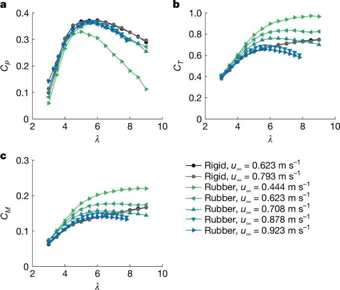
a–c, Time-averaged coefficients of power (a), thrust (b) and root bending moment (c) as a function of the tip-speed ratio for rigid and flexible blades at different flow speeds.
Performance over a tidal period
To quantify the practical benefits of the passive load mitigation of the chordwise-flexible blade in realistic inflow, we simulate the performance over a representative tidal cycle and compare it against a rigid blade turbine with the same control strategy and a state-of-the-art, actively pitch-controlled turbine (see Supplementary Note 2 for modelling of the active pitch-and-speed control turbine). The sinusoidal inflow velocity represents the flow seen by a tidal turbine during a tidal cycle is shown in Fig. 2a, which is
where τ is the tidal period.
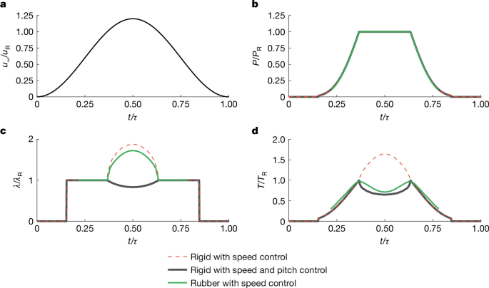
a–d, Time history over a simulated tidal period of the freestream speed (a), the quasi-steady power (b), the tip-speed ratio (c) and the quasi-steady thrust (d). Data are presented for a rigid-blade turbine with only an active speed controller, a state-of-the-art active pitch-and-speed controller, and rubber blades with an active speed controller. All data are divided by the corresponding rated value.
The cut-in velocity of the turbine is selected at u∞/uR = 0.2. The turbine operates at λ = 5.5 when the velocity is lower than rated. At the rated speed, all turbine configurations are operated at the same tip-speed ratio (λR) and provide the same quasi-steady power (PR) and thrust (TR). At higher than rated velocities, λ is such that P/PR = 1. The maximum velocity is set at u∞/uR = 1.2, representative of typical tidal turbine operating conditions.
The simulation first confirms that the passive design of the flexible blade does not compromise its primary function of energy capture. The normalized power profiles shown in Fig. 2b coincide for the rubber blade with speed control and the state-of-the-art active pitch control turbine, where the turbine speed is shown in Fig. 2c. As the total energy harvested is proportional to the integral of the power curves over the tidal cycle, the overlap of the curves confirms a negligible difference in overall energy yield. This demonstrates that the load-mitigation benefits of flexible blades can be achieved without a penalty to energy capture in a real-world setting.
The advantage of the flexible blade design is revealed by the differences in the quasi-steady thrust (Fig. 2d) between the turbine configurations. The state-of-the-art active pitch system limits structural loads by actively feathering the blades into the flow while maintaining the rated rotational speed. For a rigid blade, using only an overspeed-control strategy, the fixed geometry cannot adapt to the increasing flow; solely increasing the tip-speed ratio results in an increasing thrust that peaks at approximately 1.65 times the rated value (Fig. 2c). By contrast, with a comparable speed-control strategy, the passive system of the flexible blade achieves the same quasi-steady power and similar quasi-steady thrust as the active control.
It is also important to note that flexible blades show a slightly higher thrust coefficient at lower, off-design velocities (Fig. 1b) than the baseline rigid blade. However, the absolute thrust force, which scales with velocity squared, is smaller during these periods than the peak values over the tidal cycle. As the maximum loading dictates the primary structural design requirements of a turbine, the nearly identical peak thrust of the passive flexible blade to that of the complex, state-of-the-art active pitch system suggests comparable outcomes for turbine longevity and maintenance costs, representing a marked advancement towards more durable and cost-effective tidal energy systems. Overall, these results indicate that the chordwise-flexible blades can offer a compelling and robust alternative to the state-of-the-art active pitch-and-speed control turbine system.
High-frequency load mitigation
An effective passive system must also address high-frequency load fluctuations, which are a primary driver of fatigue damage. In this context, high frequency refers to the unsteady load components that occur at frequencies of the order of the period of revolution, such as those induced by turbulence, velocity shear or wake interaction, and so on. Figure 3 quantifies the effectiveness of the flexible blades by presenting the standard deviation of load fluctuations relative to the reference rigid blades at rated velocity. To reflect realistic conditions over a tidal cycle, the data for u∞/uR ≤ 1 are presented at the optimal tip-speed ratio (λ = 5.5) for maximum power extraction, whereas the data for conditions above the rated velocity (u∞/uR = 1.06) are presented at the higher tip-speed ratio (λ = 8) that is used to cap power. Figure 3 shows a substantial reduction of unsteady loads for all three components when the turbine is operating under its most demanding conditions. At the rated velocity (u∞/uR = 1.0), where the turbine operates at its optimal λ for maximum power extraction, the flexible blades provide effective fluctuation reduction across power, thrust and root bending moment (mitigated by approximately 18%, 23% and 28%, respectively). Furthermore, even when the inflow velocity increases beyond the rated velocity (u∞/uR = 1.06), the load fluctuation mitigation remains substantial. This demonstrates the powerful and robust damping ability of the flexible blades during both the maximum-power and power-capping phases of operation, when the absolute magnitude of fluctuating forces is greatest. At the lowest velocities (for example, u∞/uR = 0.51), where the blade operates in a stalled condition, fluctuations are known to increase relative to the rigid blade. However, their absolute magnitude is small, reaching only about 15–35% of the fluctuation level of the rigid blade at its rated velocity. A more detailed analysis, presented in Supplementary Note 3, confirms that this mitigation is robust across a wide range of tip-speed ratios under these high-flow conditions.
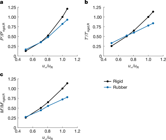
a–c, Standard deviation of power (a), thrust (b) and root-bending moment (c) of flexible and rigid blades, for the optimum tip-speed ratio (λ = 5.5). All quantities are divided by those of the rigid blade at rated velocity.
Blade shape
To illustrate the physics of the passive load regulation mechanism demonstrated previously, the deformation of the flexible blade is visualized at the tip section. Figure 4 shows the phase-averaged digital image correlation (DIC) measurements of the tip of the same flexible blade at a constant azimuthal angle, in which the blade is horizontal with downward velocity. The successful application of this technique using fully submerged cameras represents a significant experimental achievement, as most underwater DIC studies to date have been performed through observation windows rather than submerging the camera in the fluid25. In this way, complex optical distortions and refractive index mismatches associated with viewing ports are avoided, thereby achieving a more accurate measurement. In this study, the DIC system measured the deformation of the suction side of the blade. The full blade profile was then reconstructed by adding the known thickness distribution of the undeformed blade to the measured deformed chord line.
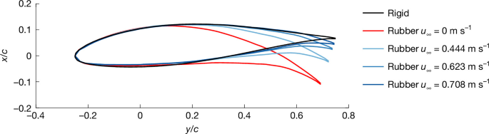
Phase-averaged profiles of one blade tip measured with DIC when the blade span is horizontal, and the tangential velocity is pointing downwards. Coordinates x, y are normalized by the chord length at the blade tip with origin at the quarter chord.
The measurements demonstrate the mechanism of the passive morphing concept. The undeformed flexible blade was designed with a significant initial camber, noticeably higher than that of the conventional rigid blade profile. The high camber present in both the initial blade shape and the subsequent deformed shape before reaching the designed operating point is the primary reason for the higher thrust force generated by the flexible blade operating off-design. Under hydrodynamic loading, the flexible trailing edge deflects upwards, causing the entire profile to flatten into a shape with less camber. This passive feathering becomes more pronounced with higher inflow velocities, which is the mechanism that reduces the thrust coefficient at high tip-speed ratios and velocities.
DIC measurements of different blades (Extended Data Figs. 1 and 2) show that blades with lower flexural rigidity undergo greater camber reduction and exhibit stronger load shedding. Specifically, for blades with the same mould geometry, a too-stiff blade results in a too-low pitch and too-high camber, and thus high mean and unsteady thrust. Conversely, a too-soft blade results in an over-pitched blade and low power capture.
The observed mean load-shedding behaviour shown in Fig. 1 arises primarily from quasi-steady passive morphing, and not from dynamic blade deformation resulting in hysteresis, vortex dynamics, and so on. DIC reconstructions of each individual blade at the same azimuthal position reveal only a narrow spread about the mean shape, corresponding to a standard deviation of the pitch variation of approximately ±0.2° (Extended Data Fig. 3).
To further verify that the mean load-shedding behaviour is due to a quasi-steady morphing, we compare the measured blade deformations (Fig. 4) and the corresponding power and thrust (Fig. 1) with those computed with an in-house fluid–structure interaction solver based on a quasi-steady low-order model (Methods). The blade shapes computed with this program are in good agreement with those measured experimentally, and so are the predicted power and thrust for different tip-speed ratios (Extended Data Fig. 4). Because the numerical solver assumes the blade is in static equilibrium under hydrodynamic loads, these results confirm that the governing physics is quasi-steady.
Scaling considerations
The fluid–structure interaction of the flexible blades is governed by two non-dimensional groups such as the Reynolds number (Re) and Cauchy number (Ca) (defined in the Methods). The experiments are performed at sufficiently high Re that the hydrodynamic load coefficients are about the same as those at full scale, as shown by the almost identical values for the rigid blade tested at different velocities in Fig. 1. To ensure geometric similarity between the model and the full-scale strain of the flexible blades, the Young modulus E of rubber must be scaled up to maintain the same Ca across scales. As discussed in Supplementary Note 4, rubber features a sufficiently high range of E for full-scale applications. Furthermore, rubber has the advantage of matching the mass density of water, enabling the design of buoyancy-neutral blades and preventing mass-related load fluctuations.
To demonstrate the scalability of the present results, numerical simulations are performed using the in-house fluid–structure interaction solver to model a utility-scale turbine. A rated speed of u∞ = 3.0 m s−1 and a 20-m diameter turbine is selected consistently with modern, state-of-the-art commercial turbines26 and typical energetic tidal sites27. Simulations performed at the respective Re and the same Ca confirm that power and thrust coefficient curves are similar at model and full scale (Extended Data Fig. 5), and therefore the present results are applicable to utility-scale turbines. Although E of the steel spar can be scaled up in numerical simulations, this is not possible in practice. Therefore, different full-scale spar design options are discussed in Supplementary Note 5.
Finally, rubber features high fatigue endurance. Preliminary calculations in Supplementary Note 6 show that the fatigue life of a full-scale rubber blade would substantially surpass the 20 years of service expected by state-of-the-art turbines.
Overall, by allowing similar control on power at thrust above rated speed than active pitch control systems, and mitigating load fluctuations, this technology offers a viable pathway to lower the LCOE. Furthermore, the reduction in load fluctuations enables deployment in energetic, highly turbulent sites previously deemed unviable due to the high fatigue loads. Further analysis of the potential industrial impact of this technology is presented in Supplementary Note 7.
Conclusions and discussion
This experimental investigation has evaluated the performance of tidal turbine flexible rubber blades with passive chordwise flexibility, compared against conventional rigid blades. Our results confirmed that the power coefficient of the flexible blade at the design tip-speed ratio is comparable to that of its rigid counterpart, demonstrating that load mitigation benefits are achieved without penalty to the primary function of the turbine as an energy harvester.
The main advantage of the flexible blades is their ability to deform, shedding the excess of load at off-design conditions. This reconfiguration allows control of power by manipulating the angular velocity of the turbine, while achieving passive mitigation of the high-frequency fluctuations that drive fatigue damage.
Therefore, the chordwise-flexible blades offer a compelling and robust alternative to state-of-the-art active pitch control. By mitigating loads with a much simpler setup, the flexible blade eliminates a significant source of potential failure and maintenance costs in offshore renewables.
The mechanism for load mitigation is confirmed through DIC measurement and a quasi-steady low-order code, which shows that the stiffness and initial geometry of the blade produce a controlled ‘feather’ as loads increase. The no-flow geometry and stiffness of the blade are designed so that, under flow conditions approaching the design point, it deforms toward the reference rigid-blade configuration.
Looking ahead, this work opens up new pathways for tidal turbine design and cost reduction. The demonstrated reductions in peak and fatigue loading could allow a reduction in structural requirements for both the blades and their supporting structure, lowering capital costs and enabling higher generator ratings, which in turn improve rated capacity per unit mass. Moreover, the increased robustness from the removal of the pitching system reduces operational and maintenance costs. These factors contribute to a lower LCOE of tidal turbines, addressing the primary barrier to the large-scale deployment of tidal energy farms. By making the technology more financially viable, this technology offers a realistic and attractive option for renewable energy production.
Methods
Experimental facility and inflow characterization
All experiments were conducted in the FloWave Ocean Energy Research Facility at the University of Edinburgh, a circular combined wave–current basin designed for scaled testing of offshore renewable energy devices. The tank has a diameter of 25 m and, for the present campaign, was operated in current-only mode with a working water depth of 1.92 m. A schematic of the facility is shown in Extended Data Fig. 6a. The experiments were performed at six inflow velocities in the range u∞ = 0.444–0.923 m s−1, corresponding to a diameter-based Reynolds number,
from 0.49 × 10⁶ to 1.16 × 10⁶, where ν is the kinematic viscosity and d is the turbine diameter. See Supplementary Note 4 for a discussion on the Reynolds number scaling.
FloWave turbulence is between 8% and 9%, and integral length scales of about 25% of the water depth28. These turbulent characteristics are consistent with energetic tidal sites such as, for example, the Fall of Warness29. There, the turbulence intensity is between 5% and 11%, with integral length scales of approximately 30–50% of the channel depth. The mean vertical shear in FloWave is approximately a power law with a 1/12 exponent (Extended Data Fig. 6b), which is only slightly weaker than the 1/10 power-law profile commonly used to represent tidal flows30. Extended Data Table 1 summarizes the comparison between FloWave and the representative tidal sites.
Turbine and blades
A three-bladed horizontal-axis turbine with a rotor diameter d = 1.26 m was installed in the tank centre, at hub height zhub = 0.876 m. The turbine is equipped with a brushless d.c. motor and a 25:1 planetary gearbox. The main components of the turbine are outlined in Extended Data Fig. 7.
The results presented in the main text refer to four sets of blades: one set of rigid blades used as a baseline and three sets of rubber blades. The baseline rigid blades are CNC-machined (SS316) using a modified NACA 63-415 hydrofoil profile along the span. The profile was modified to ensure a blunt trailing edge, as specified in ref. 31. These blades exhibited negligible flapwise and edgewise deformations. Notably, utility-scale tidal turbine blades exhibit some structural compliance. However, here the model-scale rigid blade was deliberately made rigid to provide a defined geometry.
The main text presents the results for the rigid blades and one set of rubber blades with the optimal stiffness. Conversely, the Extended Data figures also include results for the other two sets of rubber blades, with higher and lower stiffness than optimal. The flexible blades were manufactured by injecting a proprietary rubber mixture into a mould and around a steel spar. All rubber blades have the same mould geometry. See Extended Data Fig. 8 for schematics of the rubber blade. The aeroelastic properties of the blade are tailored along its span by varying the ratio of the rigid spar width to the local chord length, which increases from the tip towards the root with an average of 45%.
Instrumentation, data acquisition and uncertainty
The thrust and torque are measured by a force transducer installed between the turbine rotor and the motor shaft (Extended Data Fig. 7). The transducer is bespoke, manufactured by Applied Measurements, rated for an axial load of 1,300 N and a torque of 100 N m, and a resolution of 0.005 N and 0.0004 N m, respectively. In this study, thrust is the net force measured by the hub transducer along the streamwise direction, and torque is the net edgewise moment about the hub axis. Moreover, each blade root was instrumented with a flapwise custom root-bending-moment sensor. Calibration matrices for each sensor were obtained in situ before the test by applying known weights at four points along the cantilever beam attached to the sensor. All force signals were transmitted to a National Instruments NI 9203 acquisition system through a slip ring. The load cells were zeroed without flow before each set of measurements. For each measurement, loads were recorded at a sampling frequency of 128 Hz for 300 s. Rotor angular velocity was measured using an inductive proximity sensor that emitted one pulse per blade pass (three pulses per revolution), enabling determination of the revolution period and computation of the angular velocity.
The principal measured quantities were torque (Q), thrust (T), flapwise root-bending moment (M) and angular velocity (ω). Measured loads and power are non-dimensionalized using standard turbine coefficients:
The tip-speed ratio is defined as
where ω is the turbine angular velocity in radians per second.
Sensor accuracy and calibration uncertainties were propagated to the non-dimensional coefficients using standard bias-limit uncertainty analysis32, including thrust-torque transducer manufacturer specification (0.1% of full-scale capacity) and primary uncertainties in u∞, ω and geometric parameters. For the present setup, the maximum total bias limits is of order 10−2 for CP and of order 10−2 for CT (representative values). Supplementary Note 1 provides the full derivations and tables.
DIC and blade-shape reconstruction
Blade deformation was measured using phase-locked DIC with underwater cameras and LED illumination (LaVision). The camera system had a fixed focal length of 1.1 m and a field of view of approximately 0.87 m × 0.56 m, sufficient to capture the full blade span (0.56 m). Phase locking was achieved by using the proximity-sensor signal to trigger image acquisition as a blade passed a fixed azimuthal position, with a horizontal span and a downward tangential velocity. For each condition, between 89 and 447 instantaneous deformation fields were recorded over a 300 s period, depending on u∞ and λ.
Images were processed in LaVision DaVis 11 using a subset size of 21 × 21 pixels and a grid step size of 2 × 2 pixels, resulting in a spatial resolution of approximately 0.68 mm near the blade tip (approximately 2% of the tip chord). A reference image in quiescent water was acquired before each set of measurements. In the present configuration, DIC was used to measure the deformation of the suction-side surface of the blade. The full blade profile was reconstructed by combining the measured chord-line deformation with the known undeformed thickness distribution.
Fluid–structure interaction simulations
A bespoke fluid–structure interaction (FSI) solver was developed for the present study. The solver couples an in-house code based on blade element momentum theory (BEMT), with a panel method with an integral boundary-layer formulation (XFOIL), and a finite element analysis commercial software (Abaqus). The code uses a two-level iterative process, as schematically shown in Extended Data Fig. 9. The process begins with an initial blade geometry. In the outer loop, the BEMT solver is used to calculate the axial and tangential induction factors on a finite number of blade sections at different radial coordinates. Then, the flow velocity and angle of attack experienced by each blade section are computed. These values are used as initial conditions for the inner FSI loop. First, the pressure distributions around each blade section are computed with XFOIL. Then, the pressure distributions from each blade section are combined to obtain a three-dimensional pressure distribution on the blade, which is used as input to Abaqus, in which a new deformed shape is computed. The Abaqus model includes the steel spar. This new shape is then discretized into sections and returned to XFOIL to recalculate the pressure field. This iterative process continues until the blade shape converges. This deformed blade geometry at equilibrium is then fed back into the outer BEMT loop to update the induction factors. This entire two-level process is repeated until convergence. The power and thrust coefficients of the whole turbine are then computed by integrating the loads computed with XFOIL for each blade section and multiplying by three to account for the three-bladed turbine.
This code was used to design the stress-free mould shape for each blade stiffness, ensuring that the equilibrium blade shape matches the reference rigid blade at the design flow speed and tip-speed ratio. The model-scale simulations in Extended Data Figs. 4 and 5 are initialized with the mould geometry and use the actual stiffness of the metal spar and of the rubber. In the full-scale simulations (Extended Data Fig. 5), the stiffness of both the spar and the rubber is 10.6 times higher than at model scale to ensure that the model and full-scale Cauchy number for both the spar and the rubber is the same, where
where ρ is the fluid mass density and E is the Young’s modulus.