 Newshot
Main
At their core, materials are networks: in crystalline solids, atoms form regular lattices defined by uniform bonds, and in mechanical metamaterials, a distinct graph encodes the interactions among structural components. These graphs share a critical feature—an exceptional homogeneity of their local properties. Crystalline lattices are defined by unique bond lengths and interaction strengths, and even disordered systems such as amorphous microstructures show narrow distributions of connectivity and bond strength. Mechanical metamaterials, or architected materials, inherit this homogeneity: despite their structural diversity, they are typically governed by one or a few discrete length scales7, even in the presence of hierarchy2,8 or disorder9. Unit-cell design further enforces uniform connectivity10 and geometric compatibility constraints11,12, while plate- and shell-based architectures also rely on fixed thicknesses and uniform pore sizes13,14.
However, as network science has revealed in the past two decades, real-world networks rarely exhibit the homogeneity of crystalline or amorphous solids. Instead, systems as diverse as protein–protein interaction networks, social networks and global infrastructures such as the Internet show remarkable structural variability: node degrees span orders of magnitude and interaction strengths cover broad ranges3,4,5,6. This heterogeneity underlies their robustness15,16,17 and resilience18, facilitates dynamical processes19, and enables control through a small subset of nodes20. Even physical networks21,22,23, such as neuronal and vascular networks, whose nodes and links have material presence, are highly heterogeneous, with degrees, link lengths and strengths spanning several orders of magnitude24.
Elements of multiscale organization are also a hallmark of biological systems, defining their mechanical and transport properties. Dragonfly wings, for example, display vein lengths spanning more than three orders of magnitude, from ℓmin = 0.1 mm to ℓmax ≈ 50 mm (ref. 25). Leaves exhibit equally complex venation patterns, with length scales ranging from ℓ ≈ 10−1 mm to ℓ ≈ 103 mm and connectivity spanning roughly 3 decades26. Spider webs are made of string whose lengths extend from ℓ ≈ 1 mm to ℓ ≈ 103 mm (ref. 27), and bones represent hierarchical architectures built from rod- and plate-like elements, whose lengths range from ℓ ≈ 100 μm to ℓ ≈ 1,500 μm and thicknesses from λ ≈ 40 μm to λ ≈ 400 μm (ref. 28).
Over the past two decades, network models have provided a powerful language for describing systems whose structure spans many scales29,30,31,32. Graph-theoretic descriptions increasingly link such structural organization to mechanics in natural and engineered materials, collagen and other biopolymers33, paper34, self-assembled nanoparticles35, and composite fibre networks36. These studies show that disorder and network topology can be used to tune mechanical response37, for example, through the selective pruning of elastic networks38. Yet no generative framework exists for architected materials in which length, thickness and connectivity simultaneously span orders of magnitude, nor one predicting how this structural heterogeneity shapes mechanical performance.
To address this gap, here we introduce a design paradigm for mechanical metamaterials that leverages a network-science-based approach to generate architectures with a controlled, yet broadly varying, span of connectivities, length scales and interaction strengths. We refer to these materials as scale-rich (SR) networks, as they allow the simultaneous coexistence of lengths, thicknesses and connectivities that span orders of magnitude within the same system. Using both computational modelling and experiments, we show that SR metamaterials, governed by only two parameters, enable properties unattainable in single-scale systems: a 190-fold tunable range of elastic anisotropy across densities, stable and delocalized nonlinear deformation with high energy absorption, enhanced energy dissipation under dynamic loading, and programmable elastic-wave responses. Finally, we derive an analytical model that connects the total stored energy to geometrical features such as ligament length, thickness and degree, unveiling the mechanical role of the multiple length scales present in the system. Taken together, these results establish SR materials as a versatile platform for engineering multifunctional systems with programmable, multiscale performance. They also provide a minimal yet powerful framework for inverse design and open avenues of enquiry for network science.
The SR model
To construct an SR metamaterial, we start with a unit square domain (L = 1) and iteratively add ligaments whose thickness λ decreases with time t as λt = λ0t−α, where λ0 is the initial thickness and α is the decay exponent. The generation process consists of two steps (Fig. 1a): (1) choose a random nucleation point (xt, yt) within the L2 domain and a random angle θt; (2) grow a ligament of thickness λt from the nucleation point in both directions, defined by θt, until it intersects other ligaments or the boundary. We repeat steps 1 and 2 until a predefined time t = T or until we are unable to add new ligaments, leading to a state of jamming22,39 (see Supplementary Information, section 1.5 for more examples and Supplementary Information, section 1.8 for the implementation). Each new ligament stops at its first intersection, being fused together, resulting in a planar network without overlaps.
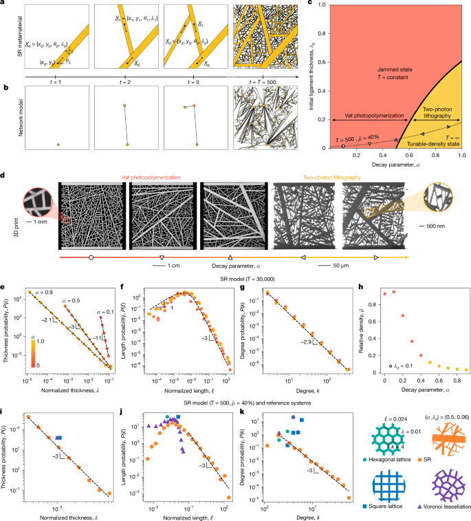
a, Generation process of an SR metamaterial, starting at time step t = 1 where an initial ligament of thickness λ0 is generated from a randomized coordinate (x0, y0) in a randomized orientation θ0. Additional ligaments are then generated at each time step t (nucleated with randomized coordinates and orientations) with thickness λt = λ0t−α, terminating at the intersection with another ligament or the domain boundary. \({X}_{i}=({x}_{i},{y}_{i},{\theta }_{i},{\lambda }_{i})\) denotes the position, orientation and thickness of the ith ligament. b, The network behind the SR metamaterial, inspired by road networks45, represents ligaments as nodes and intersections as links. The panels show the growth of the network corresponding to the configurations shown in a. c, The analytically derived (α, λ0) phase diagram (two-parameter design space) of SR metamaterials. For small α the system gets jammed, that is, it does not allow the introduction of new ligaments. For large α, the system can indefinitely accommodate additional ligaments, reaching a phase where the density of the system is tunable (Supplementary Information, section 1.1). Experimentally realized SR metamaterials with T = 500 and relative density \(\bar{\rho }=40 \% \), via two types of 3D-printing technique, are depicted with white symbols. d, Images of 3D-printed SR metamaterial specimens, at centimetre (vat photopolymerization) and micrometre (two-photon lithography) scales, corresponding to the white symbols in c. e–g, Distributions of ligament thickness P(λ) (e), ligament length P(ℓ) (f) and ligament degrees (number of connections per ligament) P(k) (g), for λ0 = 0.1; all exhibit a power-law tail. h, Relative density modulation as a function of α for λ0 = 1, averaged over 20 runs for T = 30,000. i–k, Thickness (i), length (j) and degree distribution (k) of SR metamaterials (T = 500, α = 0.5, λ0 = 0.06, averaged over 10 runs) compared with reference systems: hexagonal lattice, square lattice and Voronoi tessellation (all at \(\bar{\rho }=40 \% \)).
In the model, the length of newly added ligaments decreases with time as \({{\ell }}_{t}\approx {((1-{\sum }_{j=0}^{t-1}{{\ell }}_{j}{\lambda }_{j})/t)}^{1/2}\), as the remaining undivided area follows the recursive relation \({A}_{t}={A}_{t-1}-{\lambda }_{0}{A}_{t-1}^{1/2}{(t-1)}^{-(\alpha +1/2)}\) (Supplementary Information, section 1.1). This reduction is governed by the convergence of the sum \({A}_{t}^{\mathrm{total}}=1-{\sum }_{j=0}^{t-1}{{\ell }}_{j}{\lambda }_{j}\approx 1-{\lambda }_{0}{\sum }_{j=0}^{t-1}{A}_{j-1}^{1/2}{(j-1)}^{-(\alpha +1/2)}\), whose asymptotic behaviour defines two distinct phases (Fig. 1c): jammed and tunable-density states. If α < 1/2, or if α > 1/2 and \({\lambda }_{0} > {({{\ell }}_{0}\zeta (2\alpha ))}^{-1}\), where \(\zeta \) is the Riemann zeta function and ℓ0 ≈ 0.946 (ref. 40), the sum diverges, hence \({A}_{\infty }^{\mathrm{total}}\to 0\), resulting in complete coverage and jamming (Fig. 1c, orange area). For other parameters, the sum converges, and the system reaches a finite tunable relative density (that is, fill fraction) \(\bar{\rho }\approx {{\ell }}_{0}{\lambda }_{0}\zeta (\alpha +\beta )\), where β is the ligament length decay rate (Fig. 1c, yellow area), a phase of particular interest for lightweight materials41. As we show in Fig. 1d, systems with small α are physically realizable across length scales via additive manufacturing processes such as vat photopolymerization, whereas higher α designs require submicrometre resolution offered by two-photon lithography (Supplementary Information, section 2.2).
Both regular and irregular architectures have unique characteristic length scales, determined by either a unique or narrowly varying coordination number (degree, k), length (ℓ) and ligament thickness (λ)14,42. The distinguishing feature of an SR network is its lack of characteristic scale for any of these three defining dimensions. Indeed, as the ligament thickness follows λt = λ0t−α, the overall thickness distribution P(λ) follows the power-law distribution P(λ) ≈ λ−(1+1/α) (Fig. 1e and Supplementary Information, section 1.2).
To determine the ligament length distribution, we must consider that the ligament lengths decay as ℓt = ℓ0t−β, where β = 0.5, except at the boundary, where β = α (Supplementary Information, section 1.1.1). As we derive in Supplementary Information, section 1.3, the resulting ligament lengths follow an Erlang distribution: for high ℓ (\({\ell }\approx \sqrt{2}\)) the distribution decays as a power-law tail P(ℓ) ≈ ℓ−μ with μ = 1 + 1/β, whereas for low ℓ it increases with exponent μ = −1 (Fig. 1f).
A fundamental network characteristic is the degree (or coordination number) distribution3,4,29. It is tempting to consider each ligament intersection a node and each connecting segment a link, an approach often adopted in physical networks43,44. However, in the SR model, ligament thickness spans multiple orders of magnitude, prompting us to adopt a representation frequently used in transportation networks23,45, where each ligament (or road) is conceptualized as a single node, and intersections are represented as edges (Fig. 1b). In this representation, the degree distribution P(k) follows the power law P(k) ≈ k−γ with γ = 3 (Fig. 1g, Supplementary Fig. 11 and Supplementary Information, section 1.4). The power law emerges owing to a spatial preferential attachment29: longer ligaments have linearly more opportunities to intersect with newly added ligaments (Supplementary Fig. 11).
Taken together, we find that in SR networks, all three salient features of the system’s architecture—coordination number (degree, k), length (ℓ) and ligament thickness (λ)—follow power-law distributions. In other words, whereas in conventional material systems k, ℓ and λ are constant or vary in a very narrow range, in SR materials they span several orders of magnitude within the same sample, encoding the coexistence of many different length scales. The unique heterogeneity of the SR network raises an important question of whether SR metamaterials possess physical properties distinct from those of single-scale natural and architected materials.
SR material microstructures
We begin by determining the mechanical characteristics of SR microstructures, comparing them against three single-scale microstructures frequently used in engineering applications: the square lattice, the hexagonal lattice and the irregular Voronoi tessellation. By generating finite domains of each microstructure with a sufficiently large number of characteristic features, we confirm that the P(λ), P(ℓ) and P(k) for square and hexagonal lattices result in delta functions, whereas the Voronoi tessellation is characterized by narrow distributions (Fig. 1i–k).
To extend the comparison beyond theoretical differences between architectures, we experimentally and numerically determined the mechanical properties of these metamaterial microstructures, using vat photopolymerization 3D-printing (Methods) to fabricate centimetre-scale specimens out of elastic–plastic polymer resin (Fig. 1d, left), with a feature resolution of approximately 100 μm. We focused on SR systems with T = 500—a point where the homogenized mechanical properties show convergence and boundary effects are minimized (Supplementary Information, section 2.3). Given this feature resolution and the 500-ligament constraint, the relative densities achievable with vat photopolymerization 3D-printing ranged between \(20 \% \le \bar{\rho }\le 75 \% \) (Supplementary Information, section 2.5); we can also demonstrate lower fill fractions within the tunable-density phase (\(\bar{\rho } < 20 \% \); Fig. 1c) through the use of two-photon lithography (Fig. 1d, right) with submicrometre minimum feature sizes. Next, we characterized the linear and nonlinear mechanical responses in the quasi-static and dynamic regimes of these SR microstructures.
Highly tunable linear-elastic responses
To determine the linear-elastic response of SR metamaterials, we performed computational homogenization using the finite-element method. Imposing affine boundary conditions, we extracted a directional modulus Ed in each direction ed and calculated a non-dimensional modulus \(\bar{E}\equiv {E}_{{\rm{d}}}/{E}_{{\rm{s}}}\), where Es is Young’s modulus of the constituent material (Methods).
At a relative density of \(\bar{\rho }=40 \% \), we performed this analysis on the three single-scale systems (square, hexagonal and Voronoi) and SR geometries, demonstrated by the representative realizations in Fig. 2a, via polar representations of \(\overline{E}\) as a function of the probing direction. While the hexagonal and Voronoi structures show a near-constant \(\overline{E}\) in all orientations (that is, an isotropic stiffness response, as expected46; Fig. 2a(i),(ii)), the square lattice is highly anisotropic, displaying high stiffness parallel to its struts and minimal stiffness in any other direction (Fig. 2a(iii)). In contrast to these near extremes, we find the behaviour of the SR structures to be modulated by α: for α ≈ 0, the stiffness is nearly isotropic (Fig. 2a(iv)); and as α → 1, a principal orientation of maximum stiffness emerges (Fig. 2a(v),(vi)). Altogether, the full set of SR architectures exhibited highly tunable (an)isotropy exceeding that of the three conventional geometries combined.
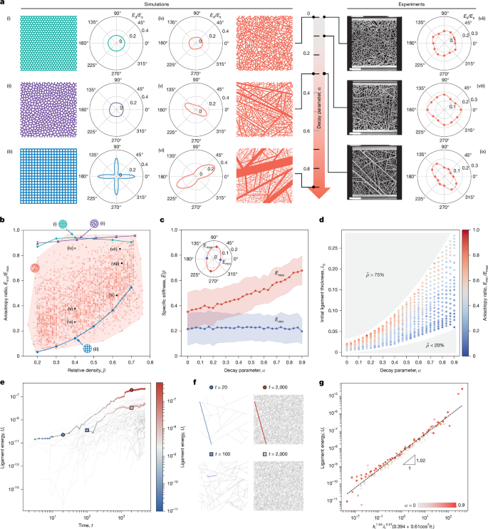
a, Directional stiffness plots of the reference hexagonal (i), Voronoi (ii) and square (iii) lattices from finite-element simulation, compared with SR samples with α = 0 (iv), α = 0.3 (v) and α = 0.9 (vi) at the same relative density. The right panels show the experimentally measured directional stiffness for SR materials with α = 0 (vii), α = 0.1 (viii) and α = 0.3 (ix), validating the theoretically predicted stiffness anisotropy. Scale bars, 10 mm. b, Anisotropy–density plot, illustrating the broad range of anisotropy achievable with the SR framework compared with the narrow range of values attained by the reference samples. The black filled circles (vii)–(ix) show the experimentally measured anisotropy. c, As the decay parameter α increases, anisotropy arises because the maximum specific directional stiffness increases, whereas the minimum specific directional stiffness is constant. The solid lines represent the mean across all samples, and the shaded regions correspond to a ±1 standard deviation from the mean value. d, Phase diagram in (α, λ0) space of the anisotropy, which functions as a design map for a tunable anisotropic response across relative densities \(0.2\le \bar{\rho }\le 0.75\). e, Temporal evolution of ligament strain energy during the SR generation process. f, Snapshots at fixed time t are shown for two example ligaments in an SR network, corresponding to the markers in e. g, Universal scaling of the ligament energy Ui as a function of the degree, ki, thickness, λi and angle, θi. For each α, data are averaged over n = 5 independent realizations, each with T = 5,000 steps.
To quantify the mechanical implications of this observed range in anisotropy across the full space of SR architectures, we plot the elastic anisotropy ratio \({\eta }_{{\rm{E}}}\equiv {E}_{\min }/{E}_{\max }\in (0,1]\), where \({E}_{\text{min}}\equiv \text{min}(\bar{E})\) and \({E}_{\text{max}}\equiv \text{max}(\bar{E})\), as a function of relative density for the reference geometries and 2,600 distinct SR microstructures with different α and λ0 (Fig. 2b). We confirm that the hexagonal lattice (0.87 ≤ ηE ≤ 0.94) and the Voronoi tessellation (0.88 ≤ ηE ≤ 0.97) remain nearly isotropic across a wide range of relative densities. For the square lattice, the anisotropy decreases from ηE = 0.03 at \(\bar{\rho }=20 \% \) to ηE = 0.55 at \(\bar{\rho }=70 \% \). By contrast, we find that the SR materials cover 77% of the available area on the density–anisotropy plot (Fig. 2b), reaching values not accessible to the reference systems. Indeed, by changing α and λ0, we can attain highly anisotropic systems (ηE ≤ 0.2) across a wide range of densities (\(17 \% \le \bar{\rho }\le 64 \% \)) as well as nearly isotropic systems (ηE ≥ 0.85) in the range \(33 \% \le \bar{\rho }\le 72 \% \). Simultaneously, we can generate systems of widely varying anisotropies at any fixed relative density: at \(\bar{\rho }=20 \% \), we span 0.04 ≤ ηE ≤ 0.78; at \(\bar{\rho }=40 \% \), we span 0.12 ≤ ηE ≤ 0.88; and at \(\bar{\rho }=70 \% \), we span 0.26 ≤ ηE ≤ 0.93. Directed growth approaches (Supplementary Information, section 2.15) further extend the achievable coverage to more than 96% of the density–anisotropy space.
To elucidate the origin of this tunable anisotropy, we plot the mass-normalized (that is, specific) minimum and maximum stiffness values (\({E}_{\min }/\bar{\rho },{E}_{\max }/\bar{\rho }\)) as a function of the decay parameter α across the entire sample set (Fig. 2c). Although the minimum specific stiffness is largely independent of α, increasing α while keeping density constant enables an increase in the maximum achievable specific stiffness, leading to robust tunability in the architecture space. This tunable anisotropy is best captured by the (α, λ0) configuration space (Fig. 2d), which shows that anisotropy increases with α and decreases with λ0. To validate our finite-element model predictions and confirm the isotropic and anisotropic responses, we performed uniaxial compression experiments across various SR geometries and orientations, confirming that at constant density increasing α directly leads to greater anisotropy (Fig. 2a(vii)–(ix), Fig. 2b, filled black circles, and Supplementary Information, section 2.7).
A scalar metric that accounts for the alignment of material along a certain loading direction indicates that the tunable directional stiffness of SR materials is the result of the inherent heterogeneity in ligament orientations and sizes. This is best captured by an orientation tensor M
where At is the area of ligament t and dt is a unit vector along its centre line. M allows us to compute a geometric anisotropy ηG ≡ μ1/μ2 ∈ (0, 1], where μ1 ≤ μ2 are the eigenvalues of M. We find that ηG agrees with the elastic anisotropy ηE (Supplementary Information, section 2.6), confirming that the anisotropy of the SR system is a direct consequence of its length-scale heterogeneity.
Tunable energy-density scaling
To understand the role of multiscale features on the measured properties, we follow two ligaments, one introduced at step t = 20 and one at t = 100, through the full generation process. As Fig. 2e shows (see Fig. 2f for the network snapshots), these ligament-specific trajectories span more than eight orders of magnitude and are irregular and rather unpredictable. Yet, as we show in Supplementary Information, section 3, the strain energy distribution across all ligaments scales with the introduction time as i−(3/4+α/2), with the degree as \({k}_{i}^{3/2+\alpha }\), with the length as \({{\ell }}_{i}^{3/2+\alpha }\), and with the thickness as \({\lambda }_{i}^{3/(4\alpha )+1/2}\) (Supplementary Fig. 46). Combining these scaling laws, we find that the elastic strain energy follows a single per-ligament law (Fig. 2g and Supplementary Fig. 47)
where f(θi) is an orientation factor, with θi being the ligament orientation. This law is, remarkably, independent of α, confirming that all scales contribute to the total energy. Plotting the per-ligament energy against the combination in equation (2) collapses all ligaments onto a single line of slope approximately 1, independent of α (Fig. 2g), confirming that all ligaments follow the scaling law equation (2).
Integrating the per-ligament law, equation (2), over the SR distributions P(k) ≈ k−3 and P(λ) ≈ λ−(1+1/α) allows us to analytically derive the scaling relation between the total elastic energy and relative density, \({U}_{\mathrm{tot}}\approx {\bar{\rho }}^{m(\alpha )}\) (Supplementary Fig. 49c), finding that the scaling exponent m depends on the SR exponent α as
where \(p(\alpha )\) is a fitted exponent describing the residual time dependence of the per-ligament energy. This expression matches the directly fitted slopes within ±0.2 (more details in Supplementary Information, section 3). The SR construction therefore interpolates continuously across the scaling map, with α as the only control parameter. These results show that the multiscale mechanics of SR networks can be reduced to a universal ligament-level energy law, which turns the growth exponent α into a macroscopic control parameter that continuously tunes the energy-density scaling response, with lower m exponents indicating more efficient mass utilization.
Delocalized nonlinear deformations
Next, we characterized the nonlinear response of SR metamaterials by conducting large-deformation uniaxial compression experiments (Methods) on the 3 reference geometries and SR systems of α = 0, chosen to minimize the impact of elastic anisotropy and emphasize the effects of the heterogeneity of ligament lengths (Fig. 3a; 3 specimens each, all at nominal \(\bar{\rho }=42 \% \); experimental results for SR systems with α > 0 are discussed in Supplementary Information, section 2.11.). Experiments on the square, hexagonal and Voronoi tessellations showed qualitative differences between each architecture (for example, in the densification strain); repeated samples of each architecture showed minimal variation (Supplementary Information, section 2.8). By contrast, all realizations of SR architectures (Fig. 3a, orange dotted lines) showed a monotonically increasing stress–strain response, coexisting with a wide envelope of responses, elucidating the tunability enabled by the SR framework and breaking the structure–response constraints observed in the single-scale reference geometries.
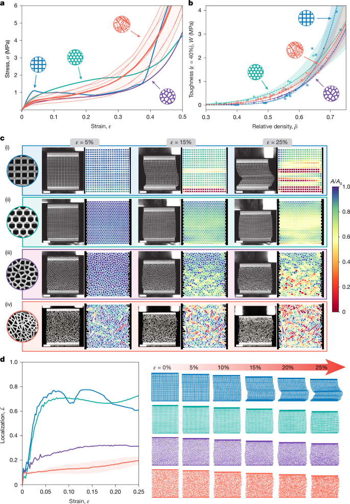
a, Experimental stress–strain curves of SR and reference samples, for \({\bar{\rho }}_{\mathrm{nom}}=42 \% \), under uniaxial compression. For the reference samples, the mean behaviour of three replicate specimens is plotted. For the SR geometries, the solid line represents the mean of all samples with α = 0, whereas the dashed curves are individual samples. The response of SR samples with α > 0 is given in Supplementary Fig. 33. b, Experimental toughness–density Ashby plot, showing the energy absorption capacity across all relative densities. c, Evolution of localized deformation with increasing macroscopic strain: still images together with computed areal Jacobians, J = A/A0, for each cell. The geometries dominated by a characteristic length scale (square lattice, (i); hexagonal lattice, (ii); Voronoi tessellation, (iii)) all develop regions of compaction where localization is observed; only the SR sample (iv) avoids the formation of compaction bands. We tracked images up to a macroscopic strain of 25%, after which compaction precludes the accurate computation of Jacobian values. Scale bars, 10 mm. d, Evolution of the localization parameter \({\mathcal{L}}\) in each geometry together with snapshots of the deformation evolution as recovered from still images. Here, the mean and standard deviation of three unique SR specimens are plotted.
From each stress–strain response, we computed the toughness, measured as the integral under the stress–strain curve to an engineering strain of 40%—before the onset of complete densification. These toughness metrics, when plotted against relative density (Fig. 3b), showcase the ability of SR architectures to match or surpass the mechanical resilience of the three reference architectures.
To understand the deformation mechanisms that lead to these benefits, we extracted still frames from the experiments and computed the areal Jacobian Ji ≡ Ai/Ai,0 of each ith cell (the relative change in void area; Fig. 3c) where Ai,0 and Ai denote the undeformed and deformed cell areas, respectively47. The square lattice was prone to buckling of vertically aligned ligaments, resulting in the observed local maxima in its stress–strain response (Fig. 3a, blue curve). Buckling events began at a single ligament, followed by a horizontal cascade of buckling events that spanned the whole length of the specimen (Fig. 3c(i)), leading to a sudden drop in its load capacity. This process repeated in a layer-by-layer fashion until the entire specimen buckled. Similarly, the hexagonal lattice (teal; Fig. 3c(ii)) also developed wide compaction bands that spanned the width of the lattice. Although the Voronoi tessellation did not succumb to well-defined shear or compaction bands owing to its lacking periodicity, consistent with previous experimental findings48, it exhibited localized compaction near the bottom, ultimately forming a domain of compacted cells that spanned the width of the specimen (purple; Fig. 3c(iii)), whereas unit cells near the top remained largely undeformed.
In contrast, SR architectures lack compaction or shear bands, which can be attributed to the local coexistence of ligaments of different lengths and thicknesses; hence, the failure of the weakest ligament in one domain will not trigger the propagation of contiguous failure pathways (Fig. 3c(iv)). To understand the origin of this diffuse damage, we computationally evaluated the susceptibility of each unsupported ligament section to buckling under a macroscopic deformation (Supplementary Information, section 2.13). We find that the network consists of ligaments characterized by a broad distribution of critical buckling loads, and hence a local buckling event does not trigger a global cascade of instability, explaining the stable macroscopic response. Moreover, selectively removing a range of length scales degrades the load-bearing capacity of the network (Supplementary Information, section 2.14), suggesting that length-scale heterogeneity underlies the robustness of the system.
To further understand this delocalization, we introduce a localization parameter
where \({\mu }_{i}\equiv \frac{1}{M}{\sum }_{j\in {{\mathcal{B}}}_{r}(i)}{J}_{j}\) is the local average Jacobian of cell i, defined over a neighbourhood \({{\mathcal{B}}}_{r}(i)\) of i containing M cells (Supplementary Information, section 2.10), and N is the total number of cells. As a result, \({\mathcal{L}}\in [0,1]\), where \({\mathcal{L}}=0\) implies that the deformation in every neighbourhood is identical—the ideal case—and \({\mathcal{L}}=1\) indicates that the deformation variation between neighbourhoods is comparable to the deformation variation among all individual cells, corresponding to extreme localization.
For all samples, \({\mathcal{L}}\) initially increases with increasing strain (Fig. 3d); the square and hexagonal lattices exhibit rapidly increasing and high asymptotic \({\mathcal{L}}\) owing to the presence of compaction bands, whereas the disordered Voronoi lattice has lower \({\mathcal{L}}\). Consistently, the SR samples show the lowest value of \({\mathcal{L}}\)—with the localization within \({\mathcal{L}}\le 0.2\) through 25% macroscopic strain, which is 37% lower than the Voronoi geometry—confirming the material’s ability to uniformly distribute damage and offer a macroscopically stable load-bearing capacity. We can further reduce \({\mathcal{L}}\) by selectively nucleating the ligaments in an SR network (Supplementary Information, section 2.12) using a ‘checkerboarding’ approach, allowing us to constrain \({\mathcal{L}}\le 0.08\) through 25% strain, representing a 74% reduction over the Voronoi value.
Efficient dynamic impact absorption
Looking beyond the quasi-static regime, an ideal impact-absorbing material maximizes the energy dissipated during the impact event while minimizing the peak force49. We performed impact experiments on SR and reference architectures at relative density \(\bar{\rho }=40 \% \), using a rigid impactor released with controlled initial energy corresponding to an instantaneous strain rate of \(\mathop{\varepsilon }\limits^{\cdot }=100\,{{\rm{s}}}^{-1}\) at impact.
Using a high-speed camera, we analysed frames during the impact event (Fig. 4a), finding that similar to the quasi-static experiments, the square lattice fails in a layer-by-layer fashion with fractured ligaments localized within sequentially forming horizontal crushing bands. The square lattice showed a sharp initial peak force that dropped to nearly zero followed by subsequent peaks corresponding to local compactions (Fig. 4b, blue curve). The hexagonal lattice also exhibited extreme localization owing to the fracture of diagonally oriented planes in as little as 2 ms post-impact. Although the Voronoi tessellation diffused damage more effectively, it also showed clear localized crush bands, leading to a high maximum force (Fig. 4b, purple curve). The SR geometry, by contrast, lacks not only well-defined crushing bands but also diffused damage through the structure, leading to the most stable force–time behaviour (Fig. 4b, orange curve), with low initial peak force and a lower compaction force than the Voronoi geometry.
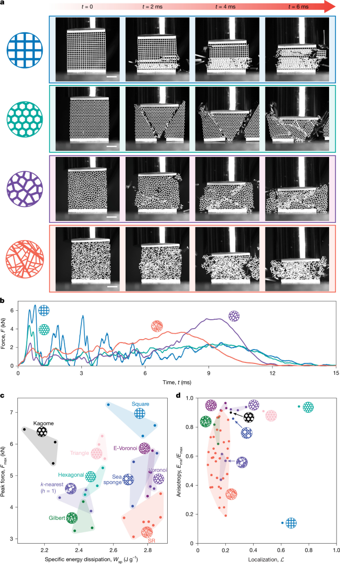
a, The SR system efficiently distributes damage under dynamic impact loading, captured by high-speed photography. Scale bars, 10 mm. b, Force–time data reveal a flat, plateau-like force–time response in the SR materials, compared with the reference architectures (square, hexagonal, triangle, sea-sponge53, and Kagome lattices; Gilbert55, Voronoi, and E-Voronoi48 tessellations; and isotropic (stretch h = 1) k-nearest foams54). c, This corresponds to simultaneous minimization of peak force and maximization of specific energy dissipation during impact. d, Anisotropy and localization under quasi-static loading. All systems have relative density \(\bar{\rho }=40 \% \). Localization corresponds to the experimentally observed value at 25% macroscopic strain and anisotropy is computed from finite-element simulations.
We extracted the overall peak force, Fmax, and the change in kinetic energy of the impactor before and after the event, representing the energy dissipated by the architecture, allowing us to measure the specific energy dissipation as
where mimpactor is the mass of the impactor, mspecimen is the mass of the specimen, and vi and vf represent the impactor velocities before and after the impact event, respectively. In Fig. 4c, we plot Wsp against Fmax, finding that the SR system occupies the optimal space with maximum specific energy dissipation Wsp and minimum peak force Fmax among all reference geometries considered in this work, indicating that the advantageous quasi-static properties of SR materials offer clear benefits under dynamic loading as well.
Steering elastic waves using SR materials
SR metamaterials also support programmable elastic-wave propagation, owing to their widely tunable elastic anisotropy, fully parameterized with only two parameters (α, λ0). To quantify direction-dependent wave propagation in SR metamaterials, we performed Bloch wave analysis on SR microstructures across the (α, λ0) design space—here reinterpreted as representative volume elements in an infinite tiling (Fig. 5a and Supplementary Information, section 2.16). Leveraging the tunability of SR metamaterials, we designed acoustic metamaterials out of quasi-isotropic SR architectures. Using the effective refractive index concept from optics neff = c0/vs, which compares the wave velocity in the constituent material c0 to the velocity vs of a wave travelling through an SR metamaterial made of the same constituent material, we find that for SR metamaterials, neff spans 1.5 ≤ neff ≤ 8.3 in the (α, λ0) configuration space, demonstrating a substantial range in achievable refractive indices compared with the hexagonal and square lattices, which span 1.0 ≤ neff ≤ 1.9 within the same relative-density limits (\(20 \% \le \bar{\rho }\le 75 \% \); Supplementary Information, section 2.17).
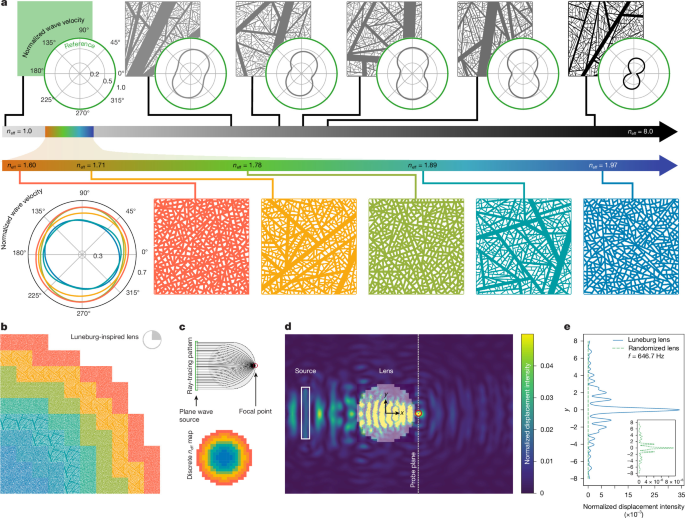
a, SR samples with their corresponding directional velocity polar plots, demonstrating a wide range of achievable space of wave velocities and anisotropy. Curves, matching the colour of their respective geometries, denote the quasi-longitudinal wave velocities, and the green curve represents the wave velocity of the monolithic material. Samples in the grey–black colour scale show the breadth of wave anisotropy achieved and the samples in the rainbow scale demonstrate isotropic SR unit cells used to construct the elastic lens in b. We use each sample as a unit cell, adding a frame with small gaps to provide boundary conditions for building the superstructure. The effective refractive index, neff, is defined as the ratio of the green to blue curves along the x direction. b, One-quarter of a Luneburg-inspired lens constructed from SR samples with varying refractive indices, highlighted by colour (blue, high refractive index; orange, low refractive index). c, Schematic illustrations of the target ray-focusing behaviour of an ideal Luneburg lens (top) and the designed refractive index profile of the full pixelated lens (bottom). d, Steady-state wavefield of the SR elastic Luneburg-like lens showing the elastic perturbation plane source (white) and focal point (red). The elastic wave is focused on the side opposite the source, as evidenced by the radial wave pattern emanating from the focal point. e, The normalized displacement intensity along the y-axis cross-section through the lens focal point (white dashed line in d). The Luneburg-like lens (solid blue curve) exhibits a sharp focal peak, whereas the randomized lens (inset, green dashed curve) shows no noticeable focusing. The residual intensity peak in the randomized lens—three orders of magnitude smaller—arises from weak energy trapping at the elastic circular boundary. A suitable excitation frequency was found in the range f ≈ 646.7 Hz, well within the long-wavelength regime of each pixel in the lens, where the refractive indices are still valid.
The refractive index tunability of SR microstructures enables multiple elastodynamic functionalities such as wave guiding or lensing, with applications in subwavelength imaging and energy harvesting50,51. We designed a Luneburg-like cylindrical lens of diameter d in a pixelated gradient-index (GRIN) approach52 (Fig. 5b and in Methods), and validated it via steady-state dynamic finite-element method, focusing elastic perturbations from an incident plane wave (Fig. 5c). Displacement fields reveal that waves traversing the lens focus on the opposite side, producing semi-circular wave fronts at the focal point and indicating that SR lenses qualitatively follow Luneburg patterns50. The displacement intensity (squared displacement magnitude) contour along the vertical line through the focal point shows a peak that is an order of magnitude larger than the side peaks, indicating energy concentration into a region approximately 0.1d wide (Fig. 5d). For comparison, a randomized reference lens constructed by randomly selecting SR cells at each radius produced a focal intensity roughly three orders of magnitude weaker, with a broader peak and side lobes of comparable magnitude, confirming that focusing arises from the GRIN arrangement of the SR pixels. Spanning such a breadth of neff enables the generation of graded materials with smoothly changing acoustic properties over a much larger range than any individual lattice family, achieved by tuning (α, λ0).
Discussion and outlook
Deviating from the single-scale restriction inherent to unit-cell-based architected materials, we drew on advances in network science to introduce and experimentally characterize SR network-based metamaterials. These architectures accommodate orders-of-magnitude variation in ligament thickness, length and connectivity while retaining control over global properties such as density and anisotropy, offering unique mechanical features inaccessible to single-scale systems: highly tunable anisotropy across densities (Fig. 2), delocalized deformation that mitigates catastrophic failure without sacrificing energy absorption (Fig. 3), and the highest specific energy dissipation at the lowest peak force among all considered periodic and disordered reference architectures under dynamic loading (Fig. 4c). Although these remarkable linear and nonlinear properties are not independently unique to SR materials, the framework’s ability to combine both sets it apart from previous architected material designs. Plotting elastic anisotropy against measured localization at \(\bar{\rho }=40 \% \) (Fig. 4d), we find that the ordered Kagome and sea-sponge53 lattices and the disordered Voronoi, E-Voronoi48, k-nearest54 and Gilbert55 systems all delocalize deformation but only near the isotropic limit (Emin/Emax ≈ 1), the triangle and hexagonal lattices remain isotropic yet localize severely (high \({\mathcal{L}}\)), and the square lattice is both anisotropic and highly localized. The SR system is thus the only family spanning the full anisotropy range (0.2 ≤ ηE ≤ 0.9) while staying delocalized, occupying a distinct performance frontier (Fig. 4c,d) well suited to adaptive load-bearing structures, protective gear (for example, helmets), packaging and armour.
Beyond these properties, SR metamaterials offer broad design flexibility (Fig. 6a) through independent control of orientation, seed density and dimensionality, enabling tailored heterogeneity that expands beyond unit-cell constraints—from filling arbitrary non-convex domains (Fig. 6b) to selectively nucleating ligaments in a manner that further minimizes localization (Supplementary Information, section 2.12) or produces extreme anisotropy (Supplementary Information, section 2.9). As a demonstration, we programmed the ligament orientation (θi = f(xi, yi)) and, inspired by the microstructure of Citrus maxima56, the radial seed-density gradient ((xi, yi) ~ ri, where ri is the radial distance of ligament i from the centre) of an SR system to divert load-transfer pathways around a fragile poly(methyl methacrylate) (PMMA) payload (Fig. 6c,d). Photoelastic imaging shows stress fringes nucleating within the payload for square and hexagonal lattices of equal density, whereas the SR system suppresses them (Fig. 6e(i)–(iii)); nonlinear finite-element simulations confirm that at identical macroscopic strain, the SR-protected payload stress is reduced by up to 4.9-fold (Fig. 6e(iv)–(vii)).
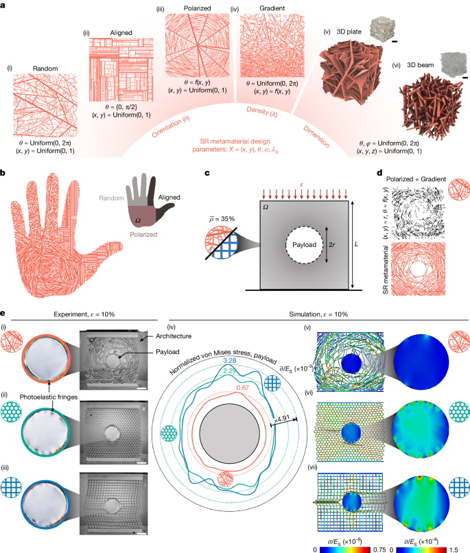
a, The SR framework enables precise control over ligament orientation, allowing the generation of random configurations where angles are selected from a uniform distribution (i), aligned networks using random selections from a prescribed set of angles (ii) and polarized patterns by sampling angles based on a predefined vector field (iii). Nucleation point positions can also be controlled to vary density across the domain, enabling gradient patterns (iv). The model further generalizes to three dimensions through the growth of plates (v) and beams (vi), where two angles specify the orientation of each plate or beam (for more examples, see Supplementary Information, section 1.5). b, SR microstructure generated within a non-convex domain Ω by combining three distinct orientation patterns—random, aligned and polarized—each applied on a different region of the domain. c, Functional design using the SR framework: a microstructure is chosen to fill a given domain under a relative-density constraint in an effort to protect a ‘payload’. d, The SR framework allows simultaneous variation of both the ligament density and orientation. A circular design inspired by the natural microstructure of C. maxima56 is shown, with a linear density gradient in the radial direction combined with a polarized orientation applied to 20% of the initial lines. e, Stress reduction in SR-protected payloads. (i)–(iii) Disk-shaped payloads made of PMMA were characterized using photoelasticity to visualize stresses under nonlinear deformation. Square and hexagonal lattices generate multiple fringes, indicating high internal stress, whereas the SR architecture shows markedly fewer fringes. (v)–(vii) Nonlinear simulations confirm these findings: the SR design reduces the average von Mises stress, \(\bar{\sigma }\), here normalized by the Young’s modulus, Es, on the embedded payload by a factor of up to 4.91 compared with the reference geometries (iv). Scale bars, 10 mm (a,e).
The sequential generation strategy of the SR system extends naturally to three dimensions by iteratively adding non-crossing plates or beams (Fig. 6a(v),(vi), yielding an analytically defined phase diagram, power-law area and degree distributions, and the same anisotropy trends as in two dimensions—anisotropy increasing with α (Supplementary Information, sections 1.6, 1.7 and 2.18), broadening the SR framework towards lightweight, robust and directionally tunable 3D metamaterials.
Finally, SR materials open opportunities for network science by revealing features inaccessible to networks without a material instantiation. Here link length and thickness—undefined or inconsequential in abstract networks—are fundamental, giving rise to phenomena, from anisotropy to stress propagation, beyond the reach of traditional network models. Taken together, these results suggest that architected network materials could open a rich domain of enquiry for network science.
Methods
Elastic homogenization
We evaluated the directional stiffness of the SR and reference geometries in the linear-elastic regime by applying computational homogenization using the finite-element method implemented with the commercial software package ABAQUS/Standard. Owing to the aperiodicity of SR geometries, classical homogenization methods relying on periodic boundary conditions do not apply. Previous approaches to extracting effective elastic properties of aperiodic materials include prescribing a displacement-controlled uniaxial strain to estimate Young’s modulus along a given direction, provided the representative volume is sufficiently large57, or applying a set of mutually orthogonal affine boundary conditions to estimate the full stiffness tensor C, which provides an approximation of effective stiffness58. Assuming that the base material is isotropic and linear elastic (with material parameters Es and νs), we adopted the latter approach to characterize the complete elastic response of the SR system. Samples were discretized using six-node, quadratic plane-strain continuum elements (CPE6) with a mesh size obtained via a mesh convergence study (Supplementary Information, section 2.4). For SR geometries, meshing was performed using an adaptive strategy where the seed size for each strut was computed based on its width. Thus, the total number of degrees of freedom and the minimum element size varied across geometries.
Sample fabrication
Samples were fabricated using vat photopolymerization using a desktop 3D-printer (Phrozen Sonic Mini 8K). Geometries generated using the model were converted into three-dimensional solid bodies by adding a prescribed, uniform thickness that yielded a plane-strain response (that is, avoiding out-of-plane deformation). To aid in experimental repeatability, the specimens were printed with monolithic top and bottom plates with a thickness equal to 5% of the height of the architecture. For the nonlinear and impact experiments, we used a commercially available resin (Anycubic Tough Resin 2.0) with a high elongation to break (for representative stress–strain curves of monolithic specimens, see Supplementary Information, section 2.1). For the experiments within the linear regime, we selected a stiffer but more brittle resin (Formlabs Clear v4) so that linear-elastic properties could be more readily extracted. In each case, we printed using the manufacturer’s recommended settings for exposure parameters at a layer height of 0.025 mm. After printing, samples were washed in isopropanol and dried in air. The dried samples were then kept in storage away from ambient ultraviolet exposure and tested 72 hours after printing.
Uniaxial compression experiments
Quasi-static compression experiments were performed on an Instron 5500 series load frame under displacement control. The lower compression platen was held fixed and the upper platen was given a prescribed downwards velocity corresponding to a (quasi-static) strain rate of 5 × 10⁻³ s−1. To perform the areal Jacobian calculations, greyscale photographs were taken at regular intervals during loading. These photographs were thresholded to separate the printed beams from void spaces. A custom image tracking script using the Python library OpenCV was used to track the areas of each void as deformation progressed.
Drop weight impact experiments were conducted using an Instron Dynatup drop tower. We used an impactor mass of 6.2 kg and a constant initial height, set to 0.8020 m above the sample, to ensure a velocity at impact of approximately 4 m s−1 (equivalently, an instantaneous strain rate of 100 s−1 at impact). We used a high-speed camera to record snapshots at 9,000 Hz during the experiment.
Elastic lens construction
We assembled a pixelated GRIN lens from SR unit cells to create a Luneburg-like cylindrical lens, which focuses a plane wave to a point image on the far side. The lens is constructed from quasi-isotropic SR representative volume elements tessellated in space to achieve a circular footprint with neff changing radially, selected from an SR library (Supplementary Fig. 42) to match the required refractive indices for each lens region. The Luneburg lens refractive index profile follows \(n=\sqrt{2-{(r/R)}^{2}}\), where r is a radial position in the lens and R is the radius of the lens; hence, the refractive index spans \(1.0\le n\le \sqrt{2}\). The circular lens footprint with R = d/2 = 2.5 is discretized into smaller pixels of side length l = 0.25, so that l/d = 0.05—this choice was made to strike a balance between lens profile accuracy and simulation complexity. We discretized the theoretical profile curve to seven distinct concentric regions equally radially spaced, whose refractive index value was calculated at the central radial location of its pixel. We constructed the lens out of quasi-isotropic SR unit cells—with minimum to maximum directional velocity ratio of vmin/vmax > 0.85—to suppress lens aberration as much as possible. Because the SR unit-cell refractive index library does not include some of the lower values of n required for the Luneburg lens, we offset the lens n profile and prioritize maintaining its absolute shape when choosing SR unit cells to fill the seven regions; this offset introduces a slight aberration but the focal point is maintained. Rigorously, we use an optimization algorithm to find the profile offset that minimizes the sum of the squared differences between the n values of the chosen unit cells and the ideal Luneburg lens with the added offset—that is, \(\min {\sum }_{i=1}^{7}{({n}_{\mathrm{pixel},i}-{n}_{\mathrm{ideal}}(r))}^{2}\) where npixel,i and nideal(r) are the refractive indices of the pixelated lens at region i and the theoretical refractive index of a Luneburg lens evaluated at that region, respectively. When assembling the lens, we add a thin disconnected border to each unit cell to ensure assembly compatibility and energy propagation between adjacent pixels. The lens was simulated in ABAQUS/Standard using a linear-elastic constituent material model. The final assembled lens was inserted into a background medium composed of the same constituent isotropic linear-elastic material, and the background was surrounded by a moderately dissipative medium which reduces reflections from its edges. The lens is excited by a plane wave of width d placed at a distance d/2 away.
Nonlinear finite-element simulations
To numerically evaluate the nonlinear behaviour of the architecture-payload system in Fig. 6, we used the finite-element method implemented with the commercial software package ABAQUS/Explicit. As in the elastic case, both the architecture and payload domains were discretized using modified six-node, quadratic plane-strain elements (CPE6M) with the same mesh density in the architecture. The architecture was modelled as elastic–plastic with hardening and the material properties were taken from experimental data (Supplementary Information, section 2.1). The rigid payload was modelled as isotropic and linear elastic with an elastic modulus 106 times that of the architecture. The compression platens were modelled as analytical rigid surfaces, with the bottom surface encastred and the top surface given a prescribed downwards velocity consistent with the experimental strain rate \(\mathop{\varepsilon }\limits^{\cdot }=5\times 1{0}^{-3}\,{{\rm{s}}}^{-1}\). We used the built-in general contact algorithm between all surfaces (including self-contact within the architecture), with a friction coefficient of 0.2 defining the tangential behaviour and a ‘hard’ pressure-overclosure condition defining the normal behaviour.